Friday 20 February 2009

microK 100

Paul Bramley - microK Project Manager: Entry 3

The microK 100 Design Team Have Their Say on the Project
It is not unusual to hear the phrase “if I had known how hard it was going to be, I wouldn’t have started this!” being voiced within the design team, usual somewhere near the end of a project… and the microK 100 project was no exception. Equally, when the project is complete, we can look back and wonder what all the fuss was about, after all the solutions to the problems that once seemed insurmountable are obvious when (at last) these problems are properly understood. These cycles of confidence, confusion, depression, euphoria and satisfaction, like the seemingly inevitable cycles in the economy, appear to be part of life (at least for the design engineer).
The original microK range was launched in 2006 with the 0.4ppm and 0.8ppm models aimed at secondary calibration and precision measurement applications and these two products have proven very successful in the market segment they targeted. However, it seems to be the curse of the design engineer that when we have a good product we can’t leave it alone and almost immediately we started to wonder what we could do to make it better. This is not, however, wasted effort as it often leads to improvements that benefit a product both technically and commercially.

So it was that we started to consider how we might achieve 0.1ppm performance and so open up the primary standards market for the microK range. The key things we needed to do were to improve the linearity of the measurement system and reduce the inherent noise of the instrument. We thought we understood what determined the performance of the original microK products and therefore what was required to achieve the target 0.1ppm performance (optimism, born of ignorance, that sowed the seeds of later frustrations!). As well as having to improve the product, we also had to put a lot of effort into improving our calibration capability. Working at the 0.1ppm level is pretty demanding and in order to discriminate linearity errors on a 0.1ppm instrument we had to be able to have a calibration capability at the 0.01ppm level.

Linearity
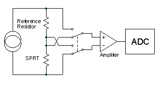
The new microK 100 uses the same substitution technique as the original microK range and therefore provides inherent zero and unity ratio stability. It is therefore only necessary to design and ADC and signal conditioning system with adequate linearity in order to achieve the target performance.

The microK 100 uses the same multi-bit sigma-delta ADC technology as before. This is a unique adaptation of the established sigma-delta technique in which the analog signal is balanced against a modulated waveform that has only two states (a 1-bit DAC). A control loop controls this DAC and ensures that the average value of the modulated waveform equals that of the analogue signal. The average value of the modulated waveform, determined using digital-signal-processing (DSP), is the output from the ADC.


Conventional Sigma-Delta ADC


Sigma-delta ADCs are readily available as single integrated circuits and provide phenomenal resolution. However, their linearity is significantly more limited than their resolution and the converted signal is inevitably quite noisy (since they rely on taking a very noise, binary signal and filtering it heavily using DSP). The microK 100 ADC is different in that it uses a 5-bit DAC in place of the 1-bit DAC in the control loop. This would not normally be feasible, since the DAC would ‘carry’ the full accuracy burden of the measurement. However, the microK 100 ADC uses pulse-width-modulation (PWM) to generate the 5-bit signal thereby converting the analog signal requirement into one of timing. In order to achieve our target 0.1ppm, we needed to be able to produce pulses whose edges have relative timing errors of 1ps (about the time it takes light or electrical signals to travel 0.3mm). It was this requirement that eventually presented the greatest design challenges (the “if only I had known…” stage). In keeping with our design philosophy, we were eventually able to do better than our target to ensure that the new product would exceed its stated performance. However, the design had to change significantly in order to improve both linearity and noise and the digital signal processing that is at the heart of the ADC changed to the point that we needed to double the size of the FPGA used to implement the functionality.


Noise
The other key performance parameter for the microK 100 is low noise. This presented an interesting challenge and eventually led to the development of a novel circuit topology. With the ADC’s low noise contribution, the microK’s overall noise performance is determined primarily by the input noise of the amplifier used to sense the small voltage developed across the PRT. This noise is generated by the amplifier’s input voltage noise and its input current noise flowing through the input impedance. Typical figures for low noise operational amplifiers (or discrete semiconductors) are around 2nVHz-½ and 0.2pAHz-½ respectively. A thermometry bridge is typically connected to a PRT with a resistance of perhaps 25Ω, in which case the voltage noise clearly dominates the result and the contribution of the current noise is truly negligible.
The best AC bridge designs use “noise impedance matching” to minimise the noise contribution of the semiconductors used in the amplifier. Since the waveforms in an AC bridge are sinusoidal, a transformer can be used at the input to the amplifier to reduce input noise at the expense of voltage noise:


Noise Impedance Matching in AC Resistance Bridges

The transformer reduces the voltage noise (referred to the input) by the turns ratio (n). Correspondingly, it increases the current noise by a factor of n. By increasing n it is possible to reduce the voltage noise at the expense of increased current noise. There is clearly an optimum value for n and this occurs when the “noise impedance”, which is defined as the ratio of the voltage to current noise (vn/in), is matched by the transformer to the input impedance, R.
This noise reduction technique can only be used with an AC resistance bridge (it cannot be used in switched DC bridges or DC current-comparator bridges) and this is one of the reasons that AC resistance bridges have historically been the instrument of choice for primary standards temperature metrology.


In developing the microK 100, we had to devise a similar noise reduction technique for use in switched DC systems. The technique involves using a number of amplifiers connected in parallel:


Noise Reduction by Parallel Analogue Processing


Each amplifier contributes linearly to the desired output signal. However, the noise from each amplifier contributes as the RMS (root of the mean squares), which is less than the linear summation of the signals. In a similar way to the noise impedance matching technique used in AC resistance bridges, we are able to reduce voltage noise at the expense of current noise by using a number of amplifiers connected in parallel (increasing n).
The microK uses a large array of amplifiers in order to reduce the voltage noise to a level that was only previously achievable using the best AC resistance bridges.


Final Thoughts
At the end of all design projects, there is a feeling of relief and achievement at having reached the technical goal. With the memory of the struggles to overcome problems encountered along the way still fresh in out minds we declare that this design is a good as it can be and resolve never to try to improve the product’s performance. Déjà-vu… this is exactly the position we were in when we launched the original microK… I wonder how long it will be before we forget the pain and look for the next technical challenge?

Monday 2 July 2007

The microsKanner

Paul Bramley - microK Project Manager: Entry 2
When the design team was first approached with a view to producing a multiplexer for the microK Thermometry Bridge , the brief was fairly ‘open’… “we just want it to be the best bridge multiplexer on the market” was the message we heard. As with all our projects, the design team went looking for ways to make the microsKanner different from its peers, not for the sake of being different but in order to give I t a competitive edge. With this in mind and the request from the sales team to make this product “the best multiplexer around” we set our main design objectives to be:


  • Performance – zero uncertainty contribution

  • Flexibility – supports all sensor types (PRTs, thermocouples & thermistors)

  • Features – individually programmable keep-warm currents for PRTs

  • Ease of use – plug-and-play… new channels added by the microsKanner just appear in the existing operator interface on the microsKanner

  • Input channels – up to 90 expansion channels

  • Reliability – completely solid-state (no relays!)

Performance
A zero uncertainty contribution sounds a little ambitious, but that was our target. In order to achieve this we could not make the microsKanner simply a ‘switch’ box’ that connects a number of inputs into one channel of the microK Bridge . Instead we had to replicate the front end input system used on the microK bridge for every channel. Each microsKanner input therefore has its own signal routing switches, active guarding system and programmable keep-warm current source. Effectively when you connect to an input on the microsKanner, you are connecting to exactly the same electronics as you would be on the main microK Bridge.

Another challenge was the switching system. Whether you use mechanical switching devices (relays) or semiconductor devices (as we do), they all have a finite on-resistance and off-resistance/leakage. The semiconductors switches used on the main microK bridge contribute very little to the overall measurement uncertainty. However, if we were to connect a further 90 input channels, in parallel, to the input system then these leakage effects would become significant. We therefore decided to use a buffered switching arrangement in which each switched channel is connected through two switches in series. When that ‘channel’ if off, the mid-point is connected via a third switch to a buffered version of the output voltage so that the voltage across the switch connected to the microK has no voltage across it and there is therefore no effect from its high (but finite) off-resistance:

The approach to the switching of thermocouples was equally robust. The inputs on the microsKanner are reversed immediately behind the input terminals during the measurement sequence in order to eliminate the effect of thermal EMFs. This is exactly the same approach as is used in the main microK Bridge to eliminate thermal EMFs. When the microK detects that a microsKanner is connected, it automatically changes from making the channel reversal at its own input terminals and changes to making these reversal at the microsKanner input. This means that thermal EMFs in the analogue connections between the microK and microsKanner are eliminated from the measurement uncertainty.

The measurement uncertainty, whether for PRTs, thermocouples or thermistors is the same whether connected directly to the microK Bridge or via the microsKanner. This means you can achieve the full performance specification of your microK bridge even when you expand the input channels using a microsKanner.

The only ‘down-side’ to this approach is that fact that it requires more switching devices. In a simple ‘switch box, you would only need four switching devices per channel. In the microsKanner we use 14 switching devices for each channel. Thankfully they are surface-mount devices and so are very small!

When we tested the microsKanner, we were pleased to discover that we could not detect any change in readings when we inserted it between the thermometer (for a 25 ohm SPRT at 1mA) and the bridge even when we took long enough averages to achieve a measurement uncertainty (2 s ) below 0.04ppm. Good enough for the task, we thought.

Ease of Use
Normally when you attach a multiplexer to an instrument, you then have the problem of how to control it. We wanted the microsKanner to be the easiest multiplexer available. In fact, all you need to do is to connect the microsKanner to your microK, which then automatically detects the microsKanner(s) (up to 9 may be connected to one microK) and the additional channels simply appear on the microK.

The expanded system is equally easy to use if you choose to control it from your PC. You simply connect your PC to the measurement system and request a measurement from the required channel, it then responds with a reading in exactly the same way as requests for readings from the microK’s three internal channels.

When you connect a number of microsKanners to a microK Bridge , the system automatically assigns channel numbers to the new inputs. An LED by each channel indicates which channel is being selected at any time to help you keep track of what it going on.

Final Thoughts
Like the original microK project, this has been an enjoyable project to work on, giving the design team the opportunity to develop some fun (and we hope useful) technology that sets the microsKanner apart from other multiplexers. We are, of course, very happy to hear what our customer think of our work so if you want to contact us with questions, comments or feedback, then please email us at microkteam @ microk.co.uk.

Thursday 1 June 2006

The microK

Paul Bramley - microK Project Manager: Entry 1 - June 2006

When we were tasked with designing the microK product in 2004, the brief was to produce a precision thermometer that measures at the sub-mK performance level and is simply the best in its class… the microK was to have the best performance (on all parameters!) and have the most comprehensive range of features. Two years on and with the microK in production, we look back on a project which has brought a lot of professional satisfaction to the team as we have pushed the performance boundaries (and ourselves) to achieve that goal. I thought it would be useful to set down some of the technical background to the microK instrument in order to shows what sets it apart.

Accuracy
Measurement uncertainty is a key parameter for any temperature metrologist. We wanted the accuracy of the microK to contribute the minimum uncertainty possible.
Other instruments working at or below 1mK uncertainty use either a DC (actually chopped DC) potentiometric measuring technique or are AC resistance bridges. We wanted the microK to work with thermocouples as well as PRTs and thermistors, so the AC bridge technique, with its excellent measuring performance, was not an option. One problem with DC instruments lies in the ADC – typically they use an integrating ADC whose linearity is fundamentally limited to a few ppm by dielectric absorption effects and the limitations of the analog circuits. The best commercially available integrating ADCs (produced by Thaler) have a linearity of 3ppm (very good, but not good enough for us) Some DC instruments use these ADCs and then ‘linearize’ the instrument in order to correct for the limitations of their ADC. But with our sights set on being the best, such an approach wasn’t acceptable - so we decided to design our own ADC. The new ADC had to have a linearity of better than 0.5ppm since it is the “measurement engine” for any instrument and we were determined not to leave the microK ‘underpowered’.
The ADC used in the microK is a unique adaptation of the established sigma-delta technique in which the analog signal is balanced again a modulated waveform that has only two states (a 1-bit DAC). A control loop controls this DAC and ensures that the average value of the modulated waveform equals that of the analogue signal. The average value of the modulated waveform, determined using digital-signal-processing (DSP), is the output from the ADC.


Conventional Sigma-Delta ADC


Sigma-delta ADCs are readily available as single integrated circuits and provide phenomenal resolution. However, their linearity is significantly more limited than their resolution and the converted signal is inevitably quite noisy (since they rely on taking a very noise, binary signal and filtering it heavily using DSP). The microK ADC is different in that it uses a 5-bit DAC in place of the 1-bit DAC in the control loop. This would not normally be feasible, since the DAC would ‘carry’ the full accuracy burden of the measurement. However, the microK ADC uses pulse-width-modulation (PWM) to generate the 5-bit signal thereby converting the analog signal requirement into one of timing. This in itself presented some interesting challenges; our sigma-delta control loop works at 100kHz in order to achieve our required 0.1s conversion time, so 0.5ppm corresponds to a timing accuracy of 5ps, or to put it in perspective, about the time it takes light/electrical signals to travel 1.5mm!. In actual fact we have been able to do better than our 0.5ppm target.

A fundamental benefit of the new ADC is its low noise. The 5-bit PWM DAC immediately reduces the noise by a factor of 32 compared with the conventional 1-bit sigma-delta approach. The new ADC therefore gave us exceptional linearity and extremely low noise… both of which are key to achieving low measurement uncertainty.

Stability
Traditionally, DC potentiometric instruments pass a common current through the device under test (DUT) and a reference resistor. A precision voltmeter is then switched between the two devices in order to measure the voltage across them and thereby determine the ratio of their resistance.


The problem with this approach is that the common-mode potential at the voltmeter input changes between the two measurements, which ultimately limits the measurement accuracy.
With the microK, we have taken an alternative approach. We have only one measurement ‘position’ into which we successively switch the DUT and reference resistor. There is then no change in common mode voltage between the measurements. Indeed the DUT and reference measurements are ‘indistinguishable’ from each other, save for the fact that they take place at different times. This “substitution” technique provides true zero drift (inherently stable).


Reliability
The sophisticated circuitry behind the microK’s performance together with its unparalleled features mean that it is one of the most complex instruments of its type. Despite this, we wanted it to have the highest reliability and to have the shortest service/repair time.
Experience shows that electronic components themselves are very reliable. Considering their complexity, modern integrated circuits have amazing reliability… basically any integration at the silicon level provides the highest possible reliability. That is why we use a Field Programmable Gate Array (FPGA) containing 150,000 gates to perform the DSP that is at the core of the ADC’s performance.


Poor reliability comes primarily from interconnections and contacts, particularly connector contacts (especially if they are not gold plated) and potentiometer wipers. That is why we banned potentiometers from the design and have just two ribbon cables (with gold plated contacts) to connect together all the PCBs in the microK. All other instruments operating at or below 1mK use relays for signal switching, which provide the primary failure source for these products. The microK uses the most modern semiconductor devices for its signal switching to lay claim to being the only 100% solid-state instrument of its type.


The electronics use modern surface-mount technology (except for a few devices that are not available in surface mount). Component soldering is made by a machine process, which is typically and an order of magnitude more reliable than conventional hand-soldered joints. To maximise reliability, the microK circuit is realised on just four printed circuit boards any of which can be replaced in less than 10 minutes, so if a microK does require service it is a quick and easy process.


With this attention to detail in the implementation of the electronics, the microK offers extremely high reliability and low cost of ownership.

Quality –The No Compromise Approach
Throughout the project, we were faced with choices about the components to use and the circuits to employ. The design team presented the options to the wider management team at design reviews and invariably the decisions went in favour of the best performance rather than the lowest cost. We have, of course, tried throughout to avoid unnecessary cost but have spent the budget for the instrument’s manufactured cost where it adds real value. That is why the microK has the best available zener references, the most stable reference resistors and a high resolution (640 x 480 full VGA) colour LCD with an industrial grade touch screen.

Tellurium Copper “Cable Pod”™ Connectors
Thermal EMFs (the EMFs generated at the junction between dissimilar metals) are a potential source of error when working at this precision. These can largely be eliminated when measuring resistance by reversing the current and averaging the measurements. That is okay for use with PRTs and thermistors, but of course is of no use when measuring temperature with thermocouples… the thermal EMFs need to be eliminated at source.


We wanted to use tellurium-copper (gold plated, of course) as the contact material, since this combines good mechanical properties with extremely low thermal EMFs against the copper terminations of a thermocouple. We also wanted the terminals to be able to accept any of the standard terminations, making it easy for users to connect any type of sensor. Whilst standard binding posts are available in tellurium-copper, we were looking for something a little better than “standard”. We settled on the Cable Pod™ connectors made by Eichmann for the hi-fi market as these accept 4mm plugs, spades or bare wires. They have other nice features, such as a clamping arrangement that doesn’t rotate as you screw down the terminal, thereby protecting the wires from mechanical damage… their features and EMF performance are ideally suited to our desire to offer the best solution.


The historical dominance of AC resistance bridges in this market means that many PRTs have BNC terminations. For this reason, we set the separation of the terminals to ¾” (19mm) allowing standard adaptors to be used for connecting BNC terminated PRTs. We wanted to make the microK as easy to use as possible.
When measuring the voltage from a thermocouple, it is common practice to reverse the input terminations and repeat the measurement in order to detect and/or compensate for any thermal EMFs or offsets inherent to the voltmeter instrument and its terminals. In the microK, we automatically reverse the input connections immediately behind the input terminals. Since we do this with solid-state switching, this does not suffer from the limitations (extra thermal EMFs) associated with doing this using relays. The user can, of course, still reverse the connections manually to gain confidence in the instrument, but it is no longer necessary to achieve low measurement uncertainty.


Final Thoughts
This has been one of the most exciting and rewarding projects I have worked on. The design team are proud to be associated with this product and hope that customers will derive as much satisfaction from using the instrument as we have from designing it. We are, of course, very happy to hear from our customers and if you want to contact us with questions, comments or feedback, then please email us at microkteam @ microk.co.uk